


Allied Warships
Check out our new extensive section on all the Allied Warships during WWII in all theatres of the war.Over 21,000 ships
In this article I hope to instruct and inform as to the building of Krick's U-25 U-boat kit. Firstly I should forewarn that this kit is not for the faint of heart. Skills in woodworking are a must, as well as working with CA (Zap, Jet or Super glue). The U-25 is dynamic diving model relying on forward motion of the motors in conjunction with the dive planes to achieve submerged running. The wooden hull with the watertight equipment compartment allows for positive buoyancy allowing for surfacing in case of malfunction or not you're sure as to where the model's position.
When I ordered this kit I was a bit na�ve, I had the preconceived notion that this kit was to be a fall together kit. Boy was I mistaken! I expected upon opening the box to see a pre-cast hull and conning tower, with miniature kit of the deck gun. Instead I was flabbergasted to see four pre-cut planks of wood with the rough outline of the hull (I do mean rough)! The deck is preformed ABS plastic with flooding slots pre-cut on the deck surface, thank goodness. The conning tower was formed in two parts on an ABS plastic sheet, which also included hatches and mount for the 8.8 gun. A sheet of brass is included for fabrication of the diving surfaces. Several sizes of brass tubing are provided to make the periscopes and the 8.8 deck gun. Krick provides two electric motors and running hardware to include universals for the prop shafts. Also there's a long heavy metal bar for the keel and ballast weight. There is a large sheet of plans and an instruction booklet that is difficult at best to follow (doesn't explain a lot on how to do things, for example making reference lines for drilling, I had to do some geometry), as there are no detailed assembly drawings. (If you're like me you're use to detailed drawings/photos of assemblies!)
Now that I've got the surprise out of the way let's get into the assembly of the kit. Using the locating dowels, glue the four pre-cut planks with epoxy resin glue, and be sure to use c-clamps with scrap wood (as not to damage the surface of the planks), set aside for 24 hours. While that was curing I turned my attention to the ABS deck, in the instruction booklet you're to split the bow and re-glue it then file it to get the correct shape of the bow. This is when I found epoxy wouldn't do and I had to use CA glue. While working on the deck you need to cut the free flood holes along the bottom edge of the deck. After making the measurements I used a Tamiya hobby saw to make the vertical cuts then with a machinist rule (metal) as straight edge and an x-acto knife made the horizontal cuts. It's tedious work but the booklet says it needs to be accomplished for the proper function of the kit. Needless to say I spread this job over a couple of sessions.
Now back to the hull, after removing the c-clamps I mounted the hull to a 2X4 to help provide a stable platform to make the all-important holes for the rudder and the dive planes. If you off set the hull on the 2X4 it will allow you to make accurate and true holes when the hull is turned on it's side for the dive plan holes. The 2X4 will maintain the hull at 90 degrees to the surface. When installing the keel weight be sure to draw a reference line down the middle of the hull you must be accurate on this. I screwed the threaded stock through the keel weight till just the tips were just showing through. When ready to make the marks for the drilling of the holes for the keel weight reference the plans for measurements. Now place the keel on the upturned hull and press the weight to the hull and the threaded stock just showing will leave impressions in the hull for drilling. Should emphasize at this time be sure to use a center punch for pilot holes to stop the drill bit from wandering.
After drilling the holes it's time for the inevitable shaping of the hull. Using the plans I transferred measurements from the side drawing to the bow and stern. With the measurements in place I free handed the profile of the bow and stern. At this time the 2X4 is still attached to the hull, this helps in sanding by affording a good handhold. I took the hull to a friend who works in a wood shop who sanded the profile on a very large disc sander. Now it's time to install the motors and the shafts into the hull, the reason for this is there are two slots for the stuffing boxes. The motors have to be installed and universals with locking sleeves to hold the stuffing boxes in place while you glue them into the hull. After the glue had set I mixed saw dust and fine shavings with Elmer's glue to fill in the slots for shaping. Having got that out of the way you'll need to transfer the contour templates to some very stiff poster boarder. These are a must so you can get an accurate contour of the hull during shaping, you'll be checking the contour quite often to make sure your not whittling away to much wood. I used a wood plane to rough out the contour of the hull, checking after each pass with the templates. NOTE: on top of the hull mark the template locations, reference the plans for their location. The hull is roughed out, now go back and start the sanding process starting with medium grit as the wood is soft tropical wood ending with very fine grit.
We're not ready to seal the wood up at this time; it's time to shoot a coat of primer to reveal flaws that were invisible. With the coat of primer done now check for flaws such as shallow depressions where you may have removed a bit too much wood. I used Elmer's exterior wood filler; it goes on easy and sands easy and takes a finish very well. After several applications of primer and necessary corrections, I gave the hull a final light sanding in preparation for sealing the wood. Before sealing I put the sleeves that will house the shafts for the dive planes and the rudder in place with a slight coating of epoxy. For sealing the wood hull I used Varathane's polyurethane clear coat exterior grade, I applied three coats lightly sanding between coats. For a flawless and blemish free surface after the last coat I gave the hull a light going over with fine steel wool. At this time mount the keel to the hull, make sure the keel is firmly seated. Then inside the equipment compartment glue the thread stock to the hull. Now for a tough coat, I used Krylon's epoxy spray paint used for kitchen appliances, it works nicely to protect against minor bumps and scratches. Then I painted the hull red then painted a black waterline. Be sure to keep the sleeves for the dive planes and rudder clean of build-up. (While coating with Varathene and painting I passed pipe cleaners through the sleeves).
Next step is to build up the conning tower assembly, this I found to be frustrating. When cutting the tower halves from the ABS sheet there is no defined cut marking, so I cut mine out large trimming down till I got the proper profile of the tower. I clued the halves together with CA glue, then filled the seams with contour putty and sanded to shape. The deck for the bridge/wintergarten is tricky to place into the tower. I messed mine up and had to use evergreen plastic sheet, after I'd made a template from the tower I had built. When this was glued in place and the step where the periscopes are to be mounted I worked on some details. I scratch built the two spray deflectors then added rungs and grab handles. For the wintergarten railings I used the supplied cotter pins but used stiff wire to fabricate the railings. The periscopes were built up using the supplied brass tubing and blended to shape after applying epoxy putty to the joints. After drilling the holes for the periscopes on the conning tower I glued them in place with CA. I didn't mount navigation lights as none were supplied with my kit; in the future I'll add them.
For the equipment compartment you have to make a lid from two pieces of supplied hobby plywood. After gluing them together I sealed the lid with three coats of Varathene. When the coats were dried I painted the upper surface black. After that dried I flipped the lid over and cut a V channel around the edge to glue in the rubber cord. Be sure to drill the three holes for the thread stock that extends from the keel weight. Make a reference mark down the center of the lid then take measurements from the plans.
Now for the diving planes and rudder, these are to be fabricated from the supplied brass sheet. The instructions don't give any ideas as to how this is to be done. What I did was to make templates from the plans then to trace the outline on the brass with a permanent marker. I cut the surfaces out with a fine hacksaw blade then filed the cuts smooth. I roughed the surfaces then primed and then painted them. I installed the shafts into the hull then measured the positions for the planes and rudder then removed just enough paint on the surfaces to mount to the shafts. After gluing into position I touched up the areas with paint.
Time for the linkages. The kit supplies rods and sleeves for the linkages with clevis. The idea is for the rod to slide inside the sleeve with watertight collars at either end of the sleeve. I lubricated the rods with mineral oil, as it won't attack the plastic. Once the linkages are in place you need to fit the compartment lid in place to see where you need to fill in the channels for the linkages. I filled in the channels using two-part epoxy putty.
To mount the deck to the hull you need to drill two holes into the hull for the mount screws. I set the screws with epoxy then fabricated two mounting blocks, which slip over and then glued to the hull. With that done I used measurements from the hull to transfer to the deck for drilling (measure twice, drill once). I painted the deck and conning tower with Testors Model Master flat gull gray, then two coats of dull coat.
Finishing up I made the net cutter from scrape ABS plastic and brass rod. The deck gun was made from supplied brass tubing, a breechblock from the parts box and some brass rod. I used the drawings to position the hatches and buoy. I made the jumpers from supplied string, which I seized with glue to stop the fuzz associated with string. The insulators are beads glued in place with cryo using the plans for placement. NOTE: I did the jumper as single from the cutter to just in front of the tower where it Y's and splits to two going down either side of the tower. The plans show ttwo all the way from cutter to the stern. To mount I used cotter pins at the stern and at the sides of the conning tower and a spring with eyelet to attach to the net cutter.
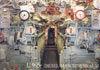
To sum up the project it was difficult to say the least. I wasn't prepared for such an under taking, though I'm pleased with the overall result. This kit, while maybe in better hands could yield up a more detailed model. My detailing skills aren't up to that caliber of scratch building. The kit gives a good approximation of a U-boat but pales in comparison to some of the really fine R/C kits with built in detail available on the market today. This kit gives me the impression of a first generation production kit (early 70s to mid 70s, maybe someone knows for sure). I don't have plans to run the U-25 as I've got the Robbe U-47 kit that I plan to build and run, the U-25 will look good on the mantle. In closing this kit should only be attempted by persons skilled in working with wood and have the time and patience to give the extra detail. Good luck, happy modeling and submarining.